|
Parts > Parts Characterization > BBa_K228258
Description
This AND Gate is designed by Christopher A Voigt(Molecular Systems Biology 3:133, 2007). We reconstructed the AND gate according to the principle of standard assembly, and finally greatly improved its efficiency. In brief, the AND gate is "open" only when both inputs are present. The AND gate accepts small molecules as inputs and integrate the signals to activate T7 promoter, so as to trigger the expression of downstream gene.
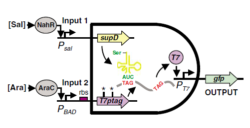 Fig1. The mechanism of the AND Gate J Christopher Anderson, Christopher A Voigt and Adam P Arkin (2007) Environmental signal integration by a modular AND gate Molecular Systems Biology 3:133The original design of the synthetic AND gate uses two promoters as input sensors and also a promoter as output. The AND gate function is obtained via an interaction between a nonsense mutated DNA and a mutation suppressor tRNA. The first promoter drives the transcription of the T7 RNA polymerase sequence which includes two internal amber codons (T7ptag) at positions 8 and 14 respectively, which is mutated from a normal codon due to base substitution. In wild-type E.coli ,the amber codon (TAG) would be decoded and thus stop the translation, producing nonfunctional polypeptide, and the double mutations can offer the lowest background level of normal T7 RNA polymerase, which would make the next step of regulation of the AND gate more convenient. And the second promoter regulates an amber suppressor gene supD, which produces a specific tRNA decoding TAG as serine. Therefore, only when both of the inputs are given, the normal T7 RNA polymerase can be synthesized, then activates the T7 promoter and express the downstream gene.
In order to make the AND gate inducible, the researchers chose two promoters that can be induced by specific small molecules. And inspired by the conception of modulation put forward by the authors, we have swapped the promoters, expecting to obtain a better AND gate. Because the core interactions between the amber mutated DNA and the suppressor tRNA are not influenced, the alternation of promoters would not change the basic AND logic behavior. In addition, we also swapped various RBSs of T7ptag to regulate the relative quantity of mutated T7 polymerase and supD tRNA and thus facilitated the screening of a better AND gate.
To see more details...
This gate is one of the best AND gates we obtained, of which T7ptagn gene is regulated by BBa_B0033 RBS.
In order to characterize the AND gate quantificationally, we placed GFP coding gene downstream of the T7 promoter and measured the output fluorescence intensity. The input promoters are activated in different degrees by varying the concentration of the arabinose and salicylate inducers from 10^-7 to 10^-3. (For more details, refer to our protocol)
Result
Table 1. Measured fluorescence intensity for each inducer concentration combination
| GFP | AraC | 1mM | 0.1mM | 10μM | 1μM | 0.1μM | 10nM | Control
|
| Sal 1mM | | 16.1848 | 17.9020 | 14.1271 | 3.8463 | 1.8941 | 1.5039 | 1.3172
|
| 0.1mM | | 12.6108 | 9.8907 | 8.6236 | 2.0183 | 1.1183 | 1.1872 | 1.2150
|
| 10μM | | 3.6933 | 3.7830 | 2.0796 | 0.8839 | 0.8816 | 0.7191 | 0.7420
|
| 1μM | | 1.3469 | 1.3210 | 1.0207 | 0.7047 | 0.9439 | 0.7955 | 0.5638
|
| 0.1μM | | 1.1872 | 1.1081 | 1.1631 | 0.9934 | 0.6558 | 0.6007 | 0.7284
|
| 10nM | | 0.9348 | 1.1029 | 0.8831 | 0.9015 | 0.9484 | 0.5325 |
|
| Control | | 1.2585 | 1.5240 | 1.1351 | 0.8763 | 0.8517 | 0.5412 | 0.7223
|
Table 2 Measured OD600 for each inducer concentration combination
| OD600 | AraC | 1mM | 0.1mM | 10μM | 1μM | 0.1μM | 10nM | Control
|
| Sal 1mM | | 0.799 | 0.727 | 0.765 | 0.736 | 0.748 | 0.755 | 0.761
|
| 0.1mM | | 0.879 | 0.757 | 0.755 | 0.775 | 0.759 | 0.761 | 0.775
|
| 10μM | | 0.883 | 0.760 | 0.745 | 0.776 | 0.780 | 0.710 | 0.731
|
| 1μM | | 1.087 | 0.794 | 0.787 | 0.781 | 0.775 | 0.766 | 0.746
|
| 0.1μM | | 0.888 | 0.763 | 0.756 | 0.751 | 0.770 | 0.740 | 0.773
|
| 10nM | | 0.909 | 0.744 | 0.732 | 0.751 | 0.693 | 0.721 | 0.770
|
| Control | | 0.886 | 0.773 | 0.767 | 0.689 | 0.759 | 0.710 | 0.747
|
Table 3 Normalized fluorescence intensity for each inducer concentration combination
| GFP | AraC 1mM | 0.1mM | 10μM | 1μM | 0.1μM | 10nM | Control
|
| Sal 1mM | 20.256 | 24.624 | 18.467 | 5.226 | 2.532 | 1.992 | 1.731
|
| 0.1mM | 14.347 | 13.066 | 11.422 | 2.604 | 1.473 | 1.560 | 1.568
|
| 10μM | 4.183 | 4.978 | 2.791 | 1.139 | 1.130 | 1.013 | 1.015
|
| 1μM | 1.239 | 1.664 | 1.297 | 0.902 | 1.218 | 1.038 | 0.756
|
| 0.1μM | 1.337 | 1.452 | 1.539 | 1.323 | 0.852 | 0.812 | 0.942
|
| 10nM | 1.028 | 1.482 | 1.206 | 1.200 | 1.369 | 0.739 | 0.915
|
| Control | 1.420 | 1.971 | 1.480 | 1.272 | 1.122 | 0.762 | 0.967
|
 Fig 2. GFP expression of AND gate, K228260: AraC-SupD-Sal-T7ptag (rbs: J44001). The data are showed for (bottom to top): 1×10^-8M, 1×10^-7M, 1×10^-6M, 1×10^-5M, 1×10^-4M and 1×10^-3M salicylate, and (left to right) 1×10^-8M, 1×10^-7M, 1×10^-6M, 1×10^-5M, 1×10^-4M and 1×10^-3M arabinose. The Z axis denotes the value of fluorescence normalized by the OD600 value. |
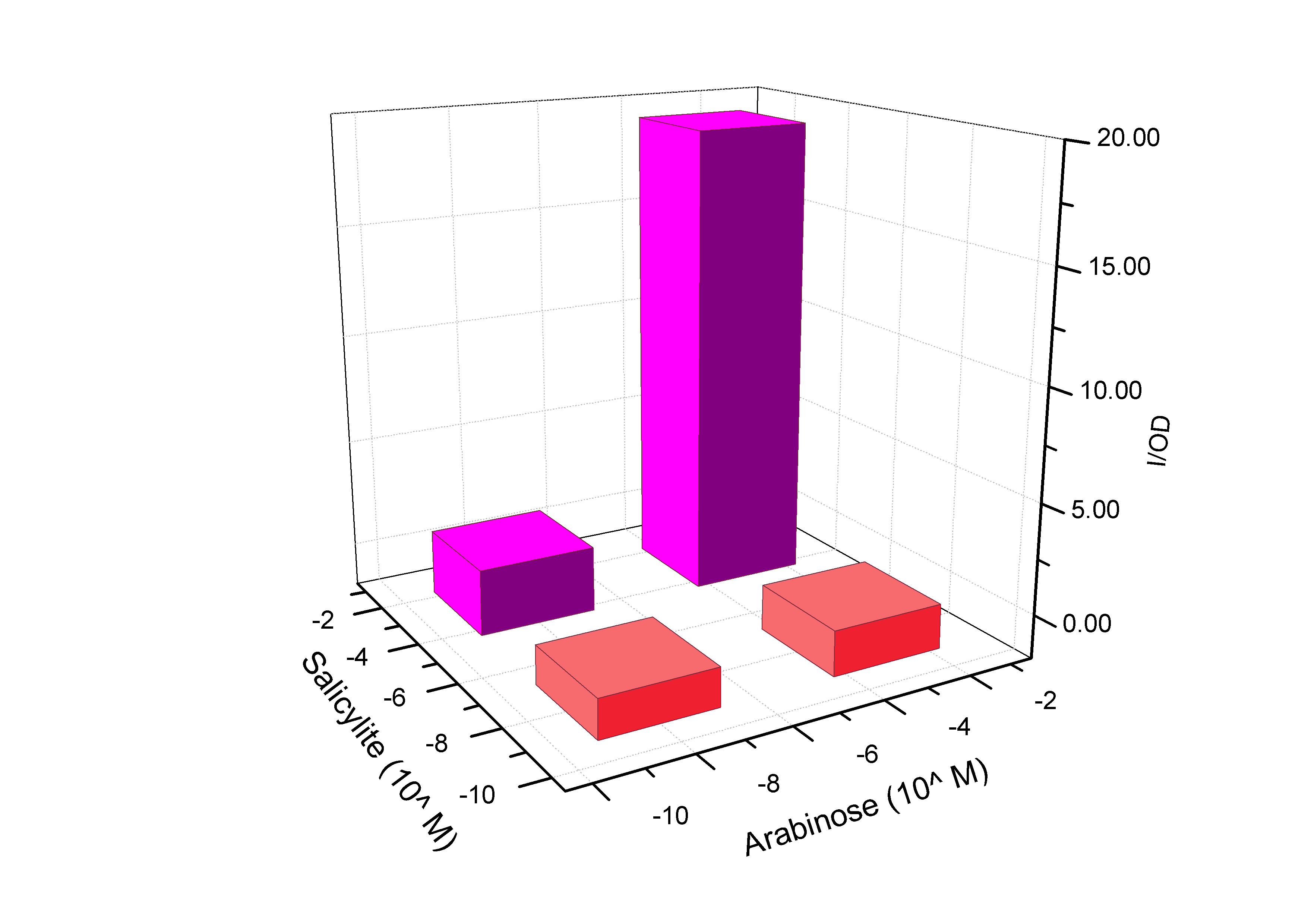 Fig 3. GFP expression of AND gate, K228260: simplified version of Fig2. The data are showed for 1×10^-8 and 1×10^-3M salicylate, and 1×10^-7 and 1×10^-3M arabinose. The concentration of 1×10^-7M is regarded as input=0, and 1×10^-3M is regarded as input=1. So the four columns show the response of (0,0), (0,1), (1,0) and (1,1). |
For more information:
refer to K228000(T7ptag) and K228001(SupD)
referrence: Anderson JC, Voigt CA, Arkin AP (2007) Environmental signal integration by a modular AND gate. Mol Syst Biol 3: 133
Safety
Because this part is from commonly used elements in bacteria. No safety problem can be arised by this part.
^Top
|
 "
"