 "
"
Team:Washington-Software/Modeling
From 2009.igem.org

| Home | Team | Project | Modeling | Notebook | Challenges | Miscellaneous |
|---|
Contents |
Mathematical Modeling
Solving Reverse Triangulation in 3-D Space with Polar Coordinate Constraints
Problem
Given the following construction and point p, or (x,y,z) find the angles θ1, θ2, and θ3.
Note that positive z is the down direction.
Constants
- TR
- Top radius
- BR
- Bottom radius
- L
- Linkage
- CA
- Control Arm
- φ1 and φ2
- Two angles
Construction
We based the mathematical construction on the physical structure of ALPHA.
From the top to the bottom:
- A circle centered at the origin with radius TR, named O
- Make three lines A1, A2, and A3 such that:
- The lines Ax are perpendicular to a tangent of O and a radius of O,
- The angle between the radii of A1 and A2 is φ1, and
- The angle between the radii of A2 and A3 is φ2.
- Make a circle centered at point p with radius BR, named P
- Find three points P1, P2, and P3 such that:
- They are on the circumference of P,
- The angle between the radius which touches P1 and the radius that touches P2 is φ1,
- The angle between the radius which touches P2 and the radius that touches P3 is φ2,
- The ray from the center of P to Px is parallel to the ray from the center of O to the point which is on Ax and O 's circumference, for all x.
- Construct three line segments CA1, CA2, and CA3 such that:
- CAx is in the same plane as Ax, for all x,
- The length of CAx is CA, and
- The angle between CAx and Ax is θx, for all x.
- The distance between Px and the end point of CAx that is not on Ax is L, for all x.
Solution
- Note that the locus of the control arms are circles of radius CA, while the locus of the linkages are spheres of radius L.
- We will calculate θ1 first, which only involves the points, circles and lines p, CA1, A1, and P1.
- Find the plane where CA1 's circle resides in. Use it to cut the sphere around P1. For future reference, call CA1 's circle C1 and the circle resulting from the cut C2
- Define xo1, for x offset, for the difference in the x coordinates of the center of C1 and the point P1.
- xo1 = TR - BR - x
- Define D1 to be the distance between the center of C1 and C2. It will also be the line connecting the centers.
- D1 = sqrt(x12 + z2)
- Obviously, D1, CA1, and linkage form a triangle. The angle between CA1 and D1 is a close approximation to θ1, but it is not exact. We will find the error in the next step. We will call this angle θ11. We use the law of cosines to calculate θ11.
- L2 = CA2 + D12 - CA * D * cos(θ11)
- θ11 = cos-1((D12 + CA2 - L2)/(2*D1*CA))
- L2 = CA2 + D12 - CA * D * cos(θ11)
- One endpoint of D1 is on A1. Thus, we can make another triangle, and the angle between D1 and A1 is the difference between θ1 and θ11. We will call this angle θ12. If we have the length of the side on A1 be z, then the last side will be xo and the triangle will be a right angle triangle. Since only xo1 changes sign in the good interval, we should use a trigonometric function that involves xo in the numerator. Thus,
- θ12 = sin-1(xo1/D1)
- θ1 = cos-1((D12 + CA2 - L2)/(2*D1*CA)) - sin-1(xo1/D1)
- θ12 = sin-1(xo1/D1)
- You just have to rotate the model φ1 degrees counterclockwise for θ2, and another φ2 degrees for θ3 using the following three dimensional rotational matrixes:
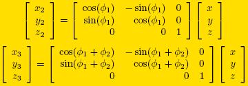
- Once you rotate the model, use steps 3-7 to get the next angles.
- θ2 = cos-1((D22 + CA2 - L2)/(2*D2*CA)) - sin-1(xo2/D2)
- θ3 = cos-1((D32 + CA2 - L2)/(2*D3*CA)) - sin-1(xo3/D3)
