Team:Alberta/Project/Automation

From 2009.igem.org

Revision as of 22:46, 21 October 2009 by Jrodway (Talk | contribs)

University of Alberta - BioBytes


DIY Automation

One of the main themes of this project, as well as iGEM in general, is the simplification of both the parts and the processes of molecular biology. This allows synthetic biology to bring relatively advanced biological techniques 'to the masses'.

The Biobytes Assembly is very rigid and reliable; however, it is also very repetitive and tedious. This has triggered us to develop an automated mechanical system (ie. a robot) capable of speeding up and simplifying our methods. The overall goal is that our robot would be simple enough to be used by high school students. This would provide a valuable tool in biological education. It is also our goal to create a system that is versatile enough to be used in more advanced research labs, thereby decreasing the time needed for plasmid construction.

The Robotic Device

Our robot is built entirely from a single Lego Mindstorms kit, using only the standard pieces and hardware sold with the kit.

  • Why use a "toy"?

    You may be wondering why we chose to use a mechanics kit made for adolescents to build our robot when there are much more sophisticated resources available? The inherent reality is that not everybody has access to a machine shop, PCB manufacturing equipment, and a micro-controller programmer. This equipment is rather expensive and not readily available to the general public. We hope that by using relatively inexpensive and readily available parts, places like high-schools and undergraduate research labs are be able to make use of our techniques.

Hardware and Software

  • Hardware

    As mentioned before, the majority of parts are from a standard Lego Mindstorm kit. In addition, rare earth magnets, a pipette tip, and electrical tape were needed to make the Lego Mindstorm kit compatible with the BioByte Assembly System.

    Inspiration

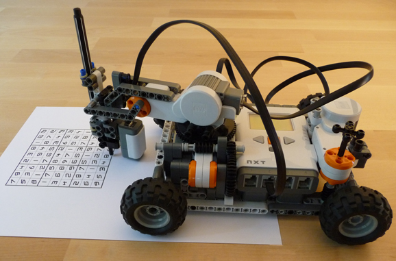
    The current physical design of the robot owes its inspiration to Hans Andersons sudoku solving robot (http://tiltedtwister.com/sudokusolver.html). Adaptation of the Anderson design allowed for the necessary amount of precision required for the 'pen' to be positioned over the well. This design has the added advantage of not possessing a large number of points where play in the gears and joints may become a problem.

    Structural Design

    The easiest and most feasible method for automating the BioByte Assembly Method involves the movement of beads from one well to the next on a 96 well plate, with each well containing a different solution, such as wash buffer or an individual byte. Therefore, as the magnet is dragged from well to well, bytes are continually added until a full length construct is generated. Another option would be to suspend the beads in one place and continually exchange the solutions surrounding the beads. However, due to the limitations of the Lego Mindstorm kit this option was not chosen. In the end, a 'dip pen' method was selected. A small rare earth magnet is secured to the end of a pipette tip, thus producing a 'pen'. The pen is then lowered into the well, whereby the beads are attracted to the magnet. The pen is then lifted up and placed in another well dragging the beads with it. The beads are then shaken off and allowed to sit in the solution whereby individual bytes may bind or the intermediate constructs are washed. This process is repeated until the full length linear construct is produced.

    Structural Obstacles

    An number of challenges had to be addressed in designing the robot.

    • The pieces come in standard lengths and sizes making it difficult to accomodate the kit to the very precise structural considerations needed for the BioBytes assembly process.
    • There is a large degree of flex to the individual pieces decreasing the rigidity and consistency of the robot.

    Software

    There was a bit more leeway with the choice of software. For this, nxtOSEK (http://lejos-osek.sourceforge.net/) was used to program the 'brains' of the robot. The instructions for installation are located here: http://lejos-osek.sourceforge.net/installation. This installation requires quite a few different steps, and a few different things to be installed, either on the robot brain, or on the programming computer. Unlike some of the other programming methods available, this one has the advantage of being free of charge.

    In order to preserve the original functionality of the robot brain, in the event that it would be used for something different later, the firmware loaded onto the brain was John Hansen's Enhanced NXT firmware (http://bricxcc.sourceforge.net/). While this did limit the size of the program that could be loaded, it was felt that it would be unlikely that the program would be large enough to strike this upper limit.

    The programming itself can be done in can be done in a few different languages, but the the language used for this implementation was C++. The nxtOSEK package provides various classes for the pieces of the NXT system (Motor, Clock, Button, etc). These classes are comprised of mainly protected data members (in the form of simple data types, mostly integers) and the methods to retrieve and set them. These data members must be protected as their values are supposed to be modified based on the automatons interaction with the physical world, and you don't really want to accidentally switch the values. This programming model allows for a high level of abstraction, allowing for more time doing really gig-taxing things like calibrating the automatons movements.

    Software design was very straightforward. Using examples provided for nxtOSEK, the syntax necessary for interacting with the motor classes was easy. The difficult part is working out the program such that the robot is able to position the dip-pen overtop of the desired well most of the time.

Getting to a Working Prototype

  • Hardware/Software Iteration

    Getting something that even sort of worked was very much just a iterative process (pictured is what one of these failed iterations in progress looks like). The most time consuming was the different physical configurations that had to be tried to come up with the current one. The hardest part was trying to come up with a way that would allow for the tip to descend with or without the magnet using only one motor.

    The script writing was also a very much iterative process (you may be familiar with the 'burn and learn' method of micro-controller programming). This was made worse by the fact that not only did the movements require calibration, but every different physical configuration required a completely (and usually radically) different calibration.

  • Calibration

    Due to the fact that no sensors were really used in the final plan for this robot, the calibration of its movement was one of the single most time consuming and aggravating parts of the whole process. Due the the fact that all the distances were 'dead reckoned' rather than sorted out on the fly, many times and distances had to be estimated and ultimately changed in an iterative process that allowed for something that came close to working. One of the problems that was discovered during this calibration process is the problem the physical set up posed with odometry. There seems to be a problem somewhere in either the motors themselves or some firmware/software issue, and the issue is such that some of the robots travelled distance 'disappears' as far as it is concerned. Due to the dead reckoning, it is vital that the robot be able to know how far it has traveled, so that it will be able to make it back, after it has traveled some distance. This is also important for it being able to accurately strike the wells, and also for staying within the boundaries of the plate.

Results

  • What it actually does:

    Surprisingly, this little automaton is actually capable of moving beads from one well to another. The magnet handily attracts the beads to the outside of the tip and pulls them out of the solution. When the tip descends without the magnet, the beads only require a little bit of agitation in order to shake them off into the liquid. The movement between the wells takes place decently, without splashing things all over the place, contaminating other wells.

    Unfortunately, it doesn't really do it reliably, and therefore hasn't been trusted with anything more than second hand beads that have already been used in BioByte construction experiments. This reliability issue is all that stands in the way of a working, inexpensive automation tool for use with the BioByte construction method.

    In order to show that it can move the beads around, a quick little experiment was done. A script was written up such that the automaton would attempt to collect beads from one well, move over to a well full of water, then drop them off. This would be repeated a bunch of times, just to see if it could do it all on its own, if it had enough tries.

    The upper photograph show the initial set up of the wells in question, with a bead solution in the center well, flanked by two wells with plain water. There is water in both flanking wells because, in all honesty I couldn't remember which way it was going to go. This also had to bonus effect of showing another potential problem associated with the reliability problems, which can be seen in the lower photograph.

    The lower photograph shows the three wells after the robot has wreaked havoc. We can see that the center well is indeed a lighter brown, indicating that there is a lower concentration of magnetic beads here. The well on the right now has a brown colour, indicating that beads did make it into this well. The well on the left also has a slight brown tint, showing that some beads made it to this well too. This occurred when the robot did something I like to call, 'going terminator,' where it missed a well and started stabbing its tip into the surrounding plastic. This causes small splashes which can cross contaminate nearby wells.

  • Problems

    • Sensitivity to initial conditions

      Since the process is dead reckoned, getting the initial setup correct is key. Even minor differences from your calibrated starting setup can send the whole process askew, with the automaton missing wells, knocking stuff over, blasting past soft-stops, wrapping cables around things, blasting cables through gears, or running itself right off the table. These events are not mutually exclusive either, so the opportunity is there to make quite the pig's breakfast out of things by not resetting the automaton's physical position to where it's brain thinks it should be.

      This problem arises from two places: the fact that the position is dead reckoned, and the fact that the automaton stores all its position information in volatile memory, meaning that once its powered down, it will have no recollection of where it is. I think that in order to solve this problem, only one of these two problems has to be solved. However, since saving to non-volatile memory may not be possible on this hardware, the only viable option may be to add sensors such that the movements are no longer dependent on a set script.

    • Odometry

      The movements of the automaton were scripted in a fashion where it was required for it to know how far it it had moved (or swiveled, or jabbed). This information was supposed to allow it move around and be able to get back to where it started, lower its tip and be able to raise it back to where it was etc. Which sorta made sense, one step forward, then one step back and you're back to square one.

      Except that it didn't really work like that. A combination of hardware (motors units themselves) and the software (motor classes provided) seemed to have led to a situation where a whole bunch of error is introduced. In tests, the unit was not capable of doing a given number of motor rotations, then after cycling the power, doing the exact same number of rotations again. It wasn't quite as bad when the power wasn't cycled, but it was still pretty rough. A workaround was attempted that involved gearing the motors down more to reduce the effect of the +/- motor rotation to something that was within tolerance. This did help, but didn't solve the problem.

      Also a problem in this department, moving 360 units does not move you the same distance as moving 60 units, 6 times in a row. The addition of sensors is likely the only/best way to get away from this odometry mess.

    • Sensitivity to power levels

      Using the battery powered NXT brick, the movements of the robot are depend somewhat on the how run down the battery is. A less than full battery really exacerbates problems that the automaton already has; they movements become sluggish and more unpredictable, meaning that it gets a whole bunch harder to have it make it to the necessary wells with any accuracy. Especially annoying, is when you didn't think of this sooner, and you keep trying to calibrate the thing. Takes forever, gets you nowhere.

      Luckily, this is probably the easiest thing to fix. The NXT brick uses 6 AA batteries in series, so 1.5 V times six batteries gives you 9 volts. A couple of alligator clips and a 120VAC to 9VDC converter will solve this problem.

  • Reliability

    The successful retrieval of beads from a solution in a well depends on a series of movements taking place. First, the tip has to be positioned over the well, then the tip lowered such that the magent also descends, then the whole assembly is lifted out of the well. A similar series of events must take place in order to introduce the beads to a new well. Tip is positioned overtop the new well, then the tip is lowered such that the magnet does not descend. Here it may be necessary to raise and lower the tip a few times in order to get the beads to come off, but it is very important that the magnet not descend during these actions, else the beads will all be picked back up prematurely. The current setup can do this, if you're wearing your lucky socks, the moon is in the right position, and there is precisely the right amount of cosmic radiation striking the planet, which is to say, not very often. To make matters worse, you never need to move beads just once, but a whole bunch of times (if you want to accomplish anything useful that is). Also, it has to be realised that any screw up in the execution of the script, and you've likely botched the whole construction. The system as it now isn't really reliable enough to trust with an unsupervised BioByte construction.

  • Conclusion:

    It works, but only sometimes. If the problem with the reliability of the system was worked out, all would be well and we'd have a nifty little, inexpensive method of automating the assembly method. In fact, I think that it won't really take too many changes to bring this little chunk of plastic, wire, and tape into something someone might actually use.

    Keeping the same general automaton design with the LEGO, minor modifications could be performed to insert better servo motors. At least for the the dip pen part. That one motor/servo switch alone would probably increase the reliability of the system ~2-3x. The other two motors could also be replaced, or the method of odometry could be improved. The switch to the voltage converter from batteries would be another change that would not only make the whole system work better, but it would also be better for the environment (the current battery operated method sorta eats batteries, it might just be because I buy the cheap kind though).

Future Work

  • Extensibility - Moving away from construction sets

    Despite all of the good things about using a construction set, it does introduce some serious limitations. To introduce more features and reliability, there are a few options. The first, and perhaps easiest, is to just get another robotic brain and set of motors. This way you can run six motors rather than the usual three, allowing you to control more things. The robotic brains are capable of communicating with each other wirelessly, so it would not be difficult to create one robotic platform that performs the desired tasks.

    Slightly more complex would be to purchase one of the third party servo controller boards that are available, along with a bunch of servos. Not only do these servo controller boards allow for the connection of more that 3 different motors, the servos that they are capable of connecting are superior in that they are able to provide more accurate positioning when compared to the motors provided with the construction set. Unfortunately, by default, these servos are not capable of full rotation, but can be purchased with the modifications predone, or the modifications can be performed yourself.

    The most complex option, would be to do away with the construction kit entirely, or at least the brains and motor parts. The physical building pieces may still be able to be used, depending on your design. Replacing the robotic brain would either be a more advanced micro-controller, or a direct connection to a computer (not really a robot anymore, but hey). The servos previously mentioned would be used for driving the motion of the machine, and would be controlled via pulse width modulation from whatever controller was being used. This option has the advantages of being the most customisable, but you definitely pay the price in monetary cost, and in complexity of design (both programming and physical design).

    The original plan for this automation project was to first use only the pieces present in the construction set to perform the 'dip-pen' method of bead movement that is presented here. The second part was use third party parts to give the robot the power to be able to dispense its own liquids, thereby allowing the beads to stay in one tube, and the liquids to be moved around. Due to time and budget constraints, the more complex robot that would be capable of moving its own liquids remains a pen and paper design.

In the event that you want to build it yourself...

  • Are you crazy?

  • More seriously:

    Source code is a work in progress and as such has not been posted here. However, the latest, most up to date version is available upon request. The physical setup is also somewhat a work in progress. Also, creating the LCad drawings would have taken forever. Should you desire building instructions, high resolution photographs can be taken from multiple angles and sent instead.