Team:Wash U/Biological Parts
From 2009.igem.org
(→Simulating a Bioreactor) |
(→Simulating A Bioreactor) |
||
| (40 intermediate revisions not shown) | |||
| Line 47: | Line 47: | ||
|[http://partsregistry.org/Part:BBa_K227010 BBa_K227010] | |[http://partsregistry.org/Part:BBa_K227010 BBa_K227010] | ||
|720 | |720 | ||
| - | | | + | |New |
| - | | | + | |New |
| - | | | + | |New |
|- | |- | ||
|Terminator | |Terminator | ||
| Line 61: | Line 61: | ||
includes prefix and suffix | includes prefix and suffix | ||
|[[media:OmpR_+_terminator.txt|sequence]] | |[[media:OmpR_+_terminator.txt|sequence]] | ||
| - | |916 | + | [http://partsregistry.org/Part:BBa_K227011 BBa_K227011] |
| - | | | + | |875/916 |
| - | | | + | |pSB1k3 |
| + | |Kanamycin | ||
|synthesized | |synthesized | ||
|- | |- | ||
| Line 78: | Line 79: | ||
|pSB1k3 | |pSB1k3 | ||
|Kanamycin | |Kanamycin | ||
| - | | | + | |New |
|- | |- | ||
|puc BA | |puc BA | ||
|[http://partsregistry.org/Part:BBa_K227006 BBa_K227006] | |[http://partsregistry.org/Part:BBa_K227006 BBa_K227006] | ||
| - | | | + | |336 |
|pSB1k3 | |pSB1k3 | ||
|Kanamycin | |Kanamycin | ||
| - | | | + | |New |
|- | |- | ||
|puc B | |puc B | ||
| Line 92: | Line 93: | ||
|pSB1k3 | |pSB1k3 | ||
|Kanamycin | |Kanamycin | ||
| - | | | + | |New |
|- | |- | ||
|puc A | |puc A | ||
| Line 99: | Line 100: | ||
|pSB1k3 | |pSB1k3 | ||
|Kanamycin | |Kanamycin | ||
| - | | | + | |New |
|- | |- | ||
| - | |OmpC promoter+ | + | |OmpC promoter+pucBA |
|[[media:OmpC_promoter_+_puc_BA.txt|sequence]] | |[[media:OmpC_promoter_+_puc_BA.txt|sequence]] | ||
| - | |539 | + | [http://partsregistry.org/Part:BBa_K227008 BBa_K227008] |
| - | | | + | |492/539 |
| + | |pSB1k3 | ||
|Kanamycin | |Kanamycin | ||
|synthesized | |synthesized | ||
| - | |||
| - | |||
| - | |||
| - | |||
| - | |||
| - | |||
| - | |||
|- | |- | ||
|Green Fluorescent Protein | |Green Fluorescent Protein | ||
| Line 155: | Line 150: | ||
|Tetracycline | |Tetracycline | ||
|high | |high | ||
| - | |||
| - | |||
| - | |||
| - | |||
| - | |||
| - | |||
| - | |||
| - | |||
| - | |||
| - | |||
| - | |||
| - | |||
| - | |||
| - | |||
| - | |||
| - | |||
| - | |||
| - | |||
| - | |||
| - | |||
|- | |- | ||
|pRKCBC3 | |pRKCBC3 | ||
| - | | | + | |~11.5kb |
|Tetracycline | |Tetracycline | ||
| - | | | + | |4 |
|}<font size="2"> | |}<font size="2"> | ||
| Line 194: | Line 169: | ||
|- | |- | ||
|[http://partsregistry.org/Part:BBa_I15010 BBa_I15010] | |[http://partsregistry.org/Part:BBa_I15010 BBa_I15010] | ||
| - | |Cph8 (resubmission) | + | |Cph8 (planned resubmission) |
|Coding | |Coding | ||
|2,238 | |2,238 | ||
| Line 217: | Line 192: | ||
|puc BA | |puc BA | ||
|Coding | |Coding | ||
| - | | | + | |336 |
|pSB1K3 | |pSB1K3 | ||
|Kanamycin | |Kanamycin | ||
| Line 231: | Line 206: | ||
|ompC+PucBA (synthesized) | |ompC+PucBA (synthesized) | ||
|Composite | |Composite | ||
| - | | | + | |492 |
|pSB1AT3 | |pSB1AT3 | ||
|Ampicilin,Tetracycline | |Ampicilin,Tetracycline | ||
| Line 243: | Line 218: | ||
|- | |- | ||
|[http://partsregistry.org/Part:BBa_K227011 BBa_K227011] | |[http://partsregistry.org/Part:BBa_K227011 BBa_K227011] | ||
| - | |RBS34+OmpR+Term (synthesized) | + | |RBS34+OmpR(sph)+Term (synthesized) |
|Composite | |Composite | ||
| - | | | + | |875 |
| - | |pSB1K3 | + | |pSB1K3 |
| - | |Kanamycin | + | |Kanamycin |
|- | |- | ||
|[http://partsregistry.org/Part:BBa_K227012 BBa_K227012] | |[http://partsregistry.org/Part:BBa_K227012 BBa_K227012] | ||
|RBS34+OmpR(sph)+Term+OmpC+PucB/A | |RBS34+OmpR(sph)+Term+OmpC+PucB/A | ||
|Composite | |Composite | ||
| - | | | + | |1375 |
|pSB1K3 | |pSB1K3 | ||
|Kanamycin | |Kanamycin | ||
|- | |- | ||
|[http://partsregistry.org/Part:BBa_K227013 BBa_K227013] | |[http://partsregistry.org/Part:BBa_K227013 BBa_K227013] | ||
| - | | | + | |ompCpro + GFP |
|Composite | |Composite | ||
|992 | |992 | ||
| - | | | + | |pSB1A2 |
| - | | | + | |Ampicilin |
|- | |- | ||
|[http://partsregistry.org/Part:BBa_K227014 BBa_K227014] | |[http://partsregistry.org/Part:BBa_K227014 BBa_K227014] | ||
|pucpro+pucBA | |pucpro+pucBA | ||
|Composite | |Composite | ||
| - | | | + | |1035 |
|pSB1K3 | |pSB1K3 | ||
|Kanamycin | |Kanamycin | ||
| Line 273: | Line 248: | ||
|RBS34+OmpR(sph)+Term+OmpC+GFP | |RBS34+OmpR(sph)+Term+OmpC+GFP | ||
|Composite | |Composite | ||
| - | | | + | |1875 |
| - | | | + | |pSB1A2 |
|Ampicilin | |Ampicilin | ||
|- | |- | ||
| Line 319: | Line 294: | ||
'''Puc Promoter'''<br> | '''Puc Promoter'''<br> | ||
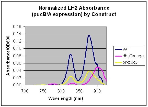
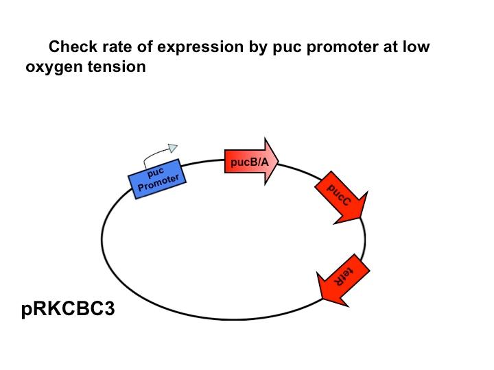
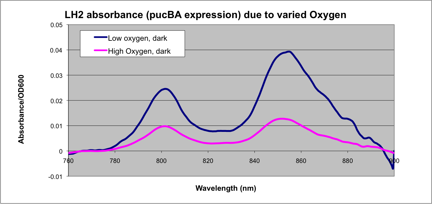
| - | [[Image: | + | [[Image:Puc Promoter slide.jpg|480px|left]] The puc promoterpromotes transcription of the LH2 pucB/A genes naturally in ''Rhodobacter sphaeroides''. It is important that we are able to compare the transcription rate of the puc promoter in the natural system vs. our mutant system so that we can determine exactly how much efficiency is gained by adding a red light sensor. The absorption spectra of a DBCOmega mutant (LH2 deficient) transformed with pRKCBC3 containing the puc promoter and pucB/A genes will allow us to characterize the puc promoter under high and low oxygen conditions. |
More absorption of light at the LH2 spectra peaks normalized to culture OD corresponds with more transcription and vis versa. | More absorption of light at the LH2 spectra peaks normalized to culture OD corresponds with more transcription and vis versa. | ||
<br> | <br> | ||
| Line 335: | Line 310: | ||
=='''Future Characterization'''== | =='''Future Characterization'''== | ||
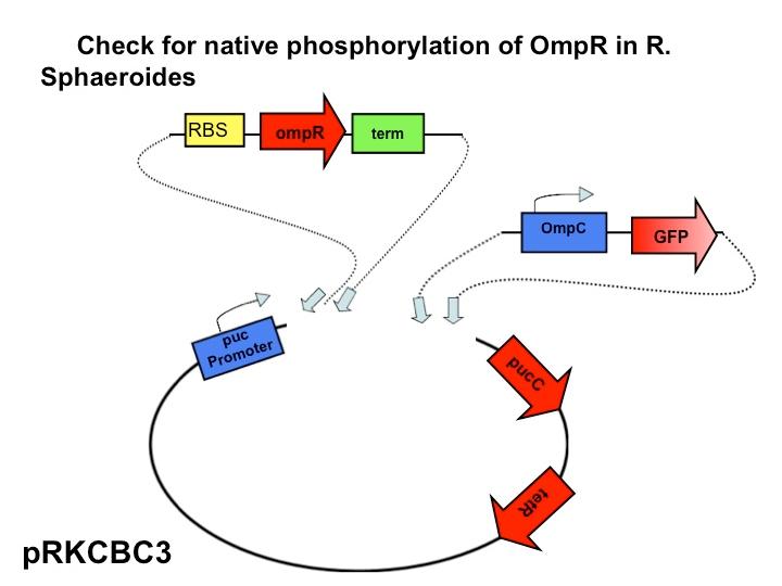
<br>[[Image:Slidex.jpg|480px|left]] The next step in our characterization of our synthetic red light response system is to analyze changes in phosphorylation of ompR in ''Rhodobacter sphaeroides''. In our final system, we only want puc genes to be transcribed and expressed via halting the autophosphorylation of ompR, not simply the puc promoter as it naturally occurs. By placing the ompR coding region downstream of the red light sensor and upstream of a terminator our modified system controls expression of the puc genes by the red light sensor. It should be impossible for the puc promoter to directly cause the transcription of puc genes due to the terminator, but instead, transcription of the puc genes must be activated via decreasing the presence of phosphorylated ompR. The end target of ompR transcription is the ompC promoter, located directly upstream of the puc genes. Placing GFP on the ompC transcript will show how often the promoter is transcribed and how often ompR is phoshorylated. | <br>[[Image:Slidex.jpg|480px|left]] The next step in our characterization of our synthetic red light response system is to analyze changes in phosphorylation of ompR in ''Rhodobacter sphaeroides''. In our final system, we only want puc genes to be transcribed and expressed via halting the autophosphorylation of ompR, not simply the puc promoter as it naturally occurs. By placing the ompR coding region downstream of the red light sensor and upstream of a terminator our modified system controls expression of the puc genes by the red light sensor. It should be impossible for the puc promoter to directly cause the transcription of puc genes due to the terminator, but instead, transcription of the puc genes must be activated via decreasing the presence of phosphorylated ompR. The end target of ompR transcription is the ompC promoter, located directly upstream of the puc genes. Placing GFP on the ompC transcript will show how often the promoter is transcribed and how often ompR is phoshorylated. | ||
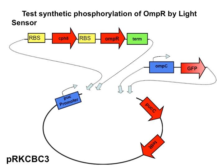
| - | <br><br><br><br><br><br><br><br><br>[[Image: | + | <br><br><br><br><br><br><br><br><br>[[Image:Characterization 1.jpg|480px|left]] Part three of our characterization measures the effectiveness of the red light sensor in downregulating the phosphorylation of ompR. This setup is identical to that of part two except we have introduced the red light sensor. Now, the rate of ompR autophosphorylation will be halted by binding to a domain on the light-activated EnvZ kinase analogue. GFP is still attached to the end product, the ompC promoter. By comparing the fluorescence of GFP in this scenario compared with the second scenario the decrease in rate of phosphorylation should be apparent due to the activity of the red light sensor. |
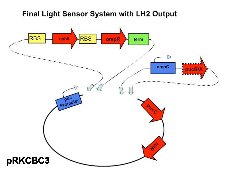
<br><br><br><br><br><br><br><br><br><br><br><br><br>[[Image:Slidez.jpg|480px|left]] This is the final construct that will be our actual functioning model in ''Rhodobacter sphaeroides''. This finished product will be compared to the wild type over various intensities of light and cell culture densities can be compared to see which strain, the wild type or the modified strain with the red light sensor was more efficient in harvesting light with varying intensities. | <br><br><br><br><br><br><br><br><br><br><br><br><br>[[Image:Slidez.jpg|480px|left]] This is the final construct that will be our actual functioning model in ''Rhodobacter sphaeroides''. This finished product will be compared to the wild type over various intensities of light and cell culture densities can be compared to see which strain, the wild type or the modified strain with the red light sensor was more efficient in harvesting light with varying intensities. | ||
<br><br><br><br><br><br><br><br><br><br><br><br><br><br><font size="2"> | <br><br><br><br><br><br><br><br><br><br><br><br><br><br><font size="2"> | ||
[https://2009.igem.org/Team:Wash_U/Biological_Parts Back To Top] | [https://2009.igem.org/Team:Wash_U/Biological_Parts Back To Top] | ||
| + | |||
| + | |||
<font size="4"> | <font size="4"> | ||
| Line 368: | Line 345: | ||
<br> | <br> | ||
<br><br><br> | <br><br><br> | ||
| - | =='''Simulating | + | =='''Simulating A Bioreactor'''== |
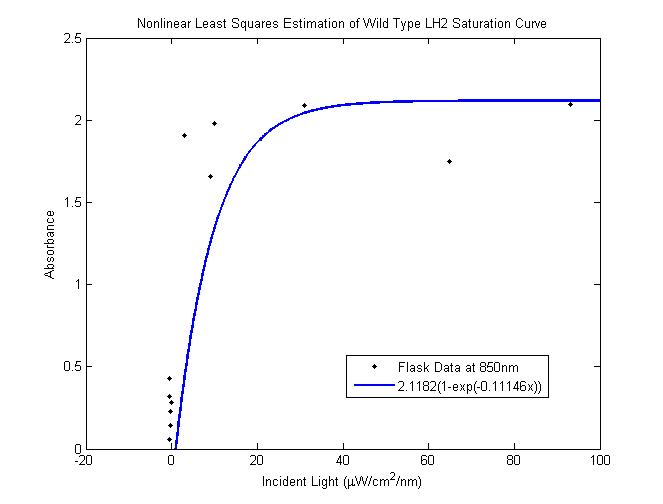
| - | < | + | Nonlinear least squares estimation of wild type saturation curve <br> |
| - | '''Problem:''' In a typical reactor, cells at the surface absorb more than enough light to saturate their photosynthetic apparatus, transmitting less energy to deeper layers. For wild type cells, the “saturation curve” is approximately the same for all cells, regardless of their incident light intensity.<br> | + | [[Image: saturation for WT as inferred.png|450px|left]] <br> |
| - | + | '''Problem:''' <br> | |
| - | + | In a typical reactor, cells at the surface absorb more than enough light to saturate their | |
| + | photosynthetic apparatus, transmitting less energy to deeper layers. Cells operating past the saturation point | ||
| + | waste incident photons by non-photochemical quenching and possibly undergo photodamage. For wild type cells, the | ||
| + | “saturation curve” is assumed to be approximately the same for all cells in all layers, regardless of their | ||
| + | incident light intensity. This means that layers of cells on the exterior of the reactor nearest a light source | ||
| + | receive an overabundance of photons and in turn block the interior layers from receiving enough light. In an | ||
| + | optimal reactor, all layers would operate near their respective saturation points to maximize the photosynthetic | ||
| + | channeling of incident light energy. | ||
| + | <br><br><br><br><br><br><br><br> | ||
| + | [[Image:Washu_eq_2.jpg|300px|left]] <br> | ||
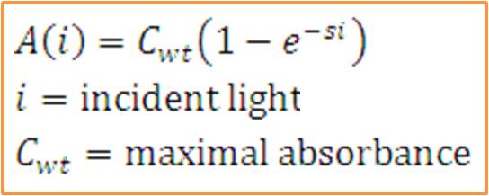
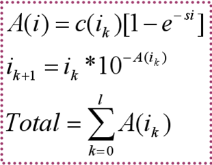
| + | The total saturation curve for wild type R. Sphaeroides was fit with a nonlinear least squares regression of the | ||
| + | form in the corresponding equation. Data points were generated from calculating absorbance as the negative logarithm of the ratio of the absolute irradiance detected on the next layer to incident absolute irradiance on a layer of cells. A logistic form was chosen to account for the diminishing returns to absorption of further photons past a threshold operating capacity of the photosynthetic apparatus. (1) | ||
| + | <br><br><br> | ||
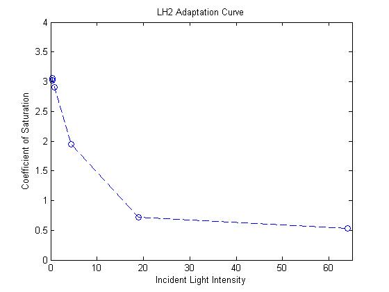
| - | - Light intensity at next layer is given by transmittance from previous layer ( | + | Exponential response curve for mutant LH2 saturation coefficients <br> |
| - | - Total energy funneled to photosynthetic pathways estimated sum of light absorbed by each layer. | + | [[image:lh2adaption.jpg|450px|left|]] <br> |
| + | '''Simulating our Mutant's advantage in a Bioreactor''' <br> | ||
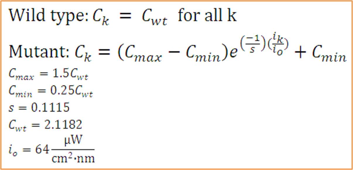
| + | For our mutant cells, the LH2 saturation curve for each layer scales as a function of light intensity. This | ||
| + | predicted behavior in the mutant is due to negative regulation of LH2 complex production as incident light | ||
| + | intensity increases. The scalar of the magnitude of the saturation curve was altered according to a predicted | ||
| + | exponential curve of LH2 production in repsone to changes in incident light. It was assumed that the system could | ||
| + | vary expression levels such that at high light intensities, the saturation curve is scaled to 25% of that of the | ||
| + | wild type. At low light intensities, LH2 production was assumed to have the potential to be up-regulated to 150% | ||
| + | of wild type expression levels. <br> | ||
| + | The advantage this mutant would confer stems from the adaptive nature of the saturation curve heights. Cells | ||
| + | receiving the most light on the outside of the bioreactor saturate at low absorption levels. This allows more | ||
| + | light to transmit to further layers, which have elevated saturation curves due to lower incident light. | ||
| + | <br> <br> <br> <br> <br> | ||
| + | [[Image:washu_eq_1.jpg|500px|center]] | ||
| + | '''Model Assumptions''' <br><br><br><br> | ||
| + | [[image:simulationequations.png|200px|left]]<br> | ||
| + | - Light intensity at next layer is given by transmittance from previous layer (assumes no backscattering).<br> | ||
| + | - Total energy funneled to photosynthetic pathways is estimated as the sum of light absorbed by each layer. This | ||
| + | generalizes to the optical density measurement of cell culture density. <br> <br> <br> <br> <br> <br> <br> | ||
| + | - The constant wild type saturation curve inherently includes both LH2 and LH1 contributions to absorbance. The | ||
| + | mutant's variable saturation curve only accounts for LH2 absorbance, since this is the only complex under the | ||
| + | light-sensing regulation. To account for the component of absorbance provided by LH1, the proportion of total | ||
| + | optical density due strictly to LH1 was investigated by comparing the growth of wild type and LH2-knockout | ||
| + | (dbcOmega) cultures. It is evident that by day three the proportion of Optical Density accounted for by LH1 | ||
| + | absorption converges to a value near 0.2. In other words, at the phase the layers of cells have grown in the model, | ||
| + | 20% of total optical density can be attributed to LH1. To account for this, the absorption in the mutant was | ||
| + | divided by the factor (1-0.2) = 0.8. Then, the total optical density of the mutant cultures reflects total | ||
| + | absorption by both LH1 and LH2. <br> <br> <br> <br> | ||
| + | Relative growth of DBComega to WT in Flask 2 at OD600 <br> | ||
| + | [[Image:relative growth.png| 600px | left]]<br> <br> <br> <br> <br> | ||
| + | - The model was revised upon gathering optical density data from the five layers of the bioreactor setup. (See | ||
| + | Results Figure 2a.) In the wild type, the optical density of the first flask of cells was much lower than | ||
| + | predicted, a phenomenon that was attributed to photodamage of the cells due to exposure to a large quantity of | ||
| + | light past the saturation point of the LH2 complexes. In the optical density data for the flasks, both the | ||
| + | dbcOmega knockout and the wild type logistically grew to an absorbance value of 1. This gave reason to put a hard | ||
| + | limit of 1 on the first flask's potential optical density. Any light left over from this cutoff was transmitted to | ||
| + | the next layer, as evidenced by in the increased growth of the second wild type flask in the Optical Density data. | ||
| + | - The response curve for the coefficient of saturation for the mutant due to changes in light intensity was modeled | ||
| + | as an inverse exponential form. In other words, the system reacts to increasing light intensity by exponentially | ||
| + | tapering the coefficient of saturation.<br> <br> <br> | ||
<br> | <br> | ||
<br> | <br> | ||
| + | <br> | ||
| + | <font size="3"> | ||
| + | <div style="text-align: center;"> | ||
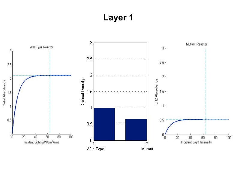
| + | Wild Type vs. Mutant Photobioreactor Simulation <br> | ||
<font size="2"> | <font size="2"> | ||
[[Image:wtvsmutsim1.jpg|450px|left]][[Image:wtvsmutsim2.jpg|450px|right]] | [[Image:wtvsmutsim1.jpg|450px|left]][[Image:wtvsmutsim2.jpg|450px|right]] | ||
<br><br><br><br><br><br><br><br><br><br><br><br><br><br><br><br><br><br><br> | <br><br><br><br><br><br><br><br><br><br><br><br><br><br><br><br><br><br><br> | ||
| - | |||
| - | |||
[[Image:wtvsmutsim3.jpg|450px|left]][[Image:wtvsmutsim4.jpg|450px|right]] | [[Image:wtvsmutsim3.jpg|450px|left]][[Image:wtvsmutsim4.jpg|450px|right]] | ||
<br><br><br><br><br><br><br><br><br><br><br><br><br><br><br><br><br><br><br> | <br><br><br><br><br><br><br><br><br><br><br><br><br><br><br><br><br><br><br> | ||
| - | |||
| + | [[Image:wtvsmutsim5.jpg|600px|center]] | ||
| + | <br><br><br><br><br><br> | ||
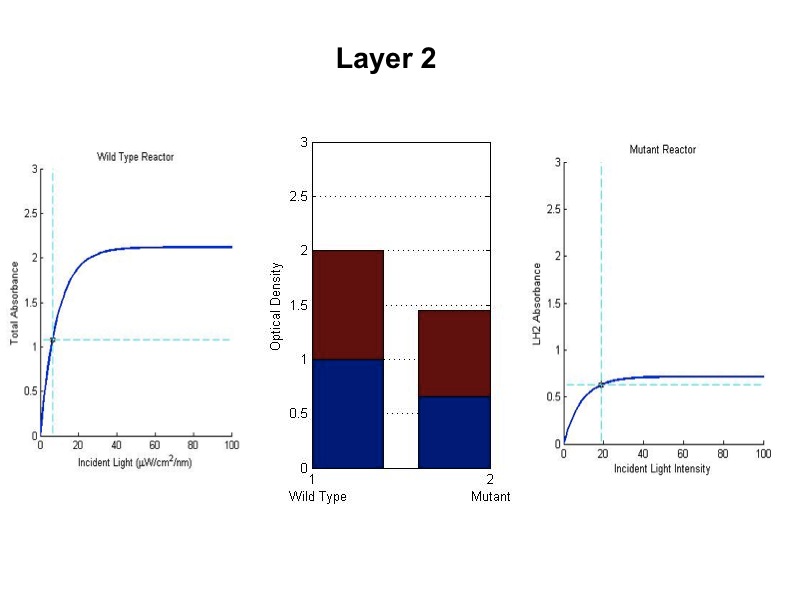
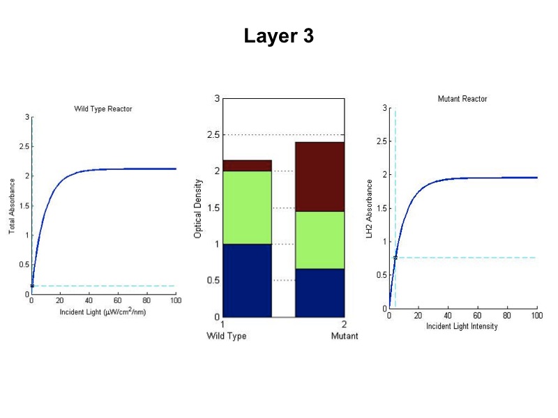
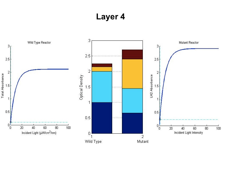
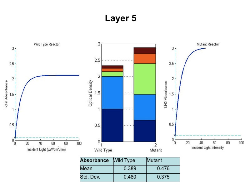
| + | The sequence of figures above shows the behavior of the static wild type saturation curve and the mutant variable saturation curve in response to incident light intensity. The dotted lines indicate the point of incident intensity and the associated absorbance with that point. The center stacked bar graph shows the accumulation of optical density given by the absorbance readings from the saturation curve. Recall that the mutant curve includes only LH2 adaptation, while the curve on the left is the total of LH1 and LH2 contributions to absorbance. Throughout the entire five layers of the bioreactor, it is evident from the simulation that the mutant achieved higher overall growth as indicated by OD. Also, the mean OD for the mutant exceeds that of wild type, and there is less variation in the levels about the mean (indicated by standard deviation). | ||
| - | + | ||
| - | <div style="text-align: | + | <div style="text-align: left;"> |
| - | + | <br> | |
| - | + | ||
| - | + | '''References''' | |
| + | |||
| + | #Steven, Spilatro R. "Photosynthesis Investigation Study." Photosynthesis Investigation Study. Department of Biology, Marietta College, Marietta, Ohio, 1998. Web. 21 Oct. 2009. <http://www.marietta.edu/~spilatrs/biol103/photolab/photosyn.html>. | ||
<div style="text-align: left;"> | <div style="text-align: left;"> | ||
Latest revision as of 03:59, 22 October 2009

 "
"
