|
Project > Logic Design
The Logic Design of our Project
Firstly, let’s consider the system as a black box. It can receive two inputs, one of which represents the ring stimulus and the other represents food. The output of the black box, correspondingly, represents dog's saliva. The food stimulus alone can cause salivation, while the ring stimulus alone can’t. After expose the system in both ring and food stimuli, the concurrence information of the two stimuli is memorized by the memory module as the core of the black box. Once the memory is generated, ring stimulus alone can also cause salivation.
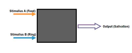 fig1. Consider the system as a black box Secondly, we should pay attention to all the functions of the system. To begin with, the food stimulus alone can lead to salivation because the food signal directly couples to the output module. Then, because when memory is on, ring stimulus can also cause salivation. Thus, we can combine the memory and the ring signal to construct an AND gate, output of the AND Gate would result in salivation. Because the output of the AND Gate and the food signal both leads to salivation, they need to pass an OR Gate before the final salivation output. After that, we need another AND Gate to detect the concurrence of the two signals, and convert it to memory.
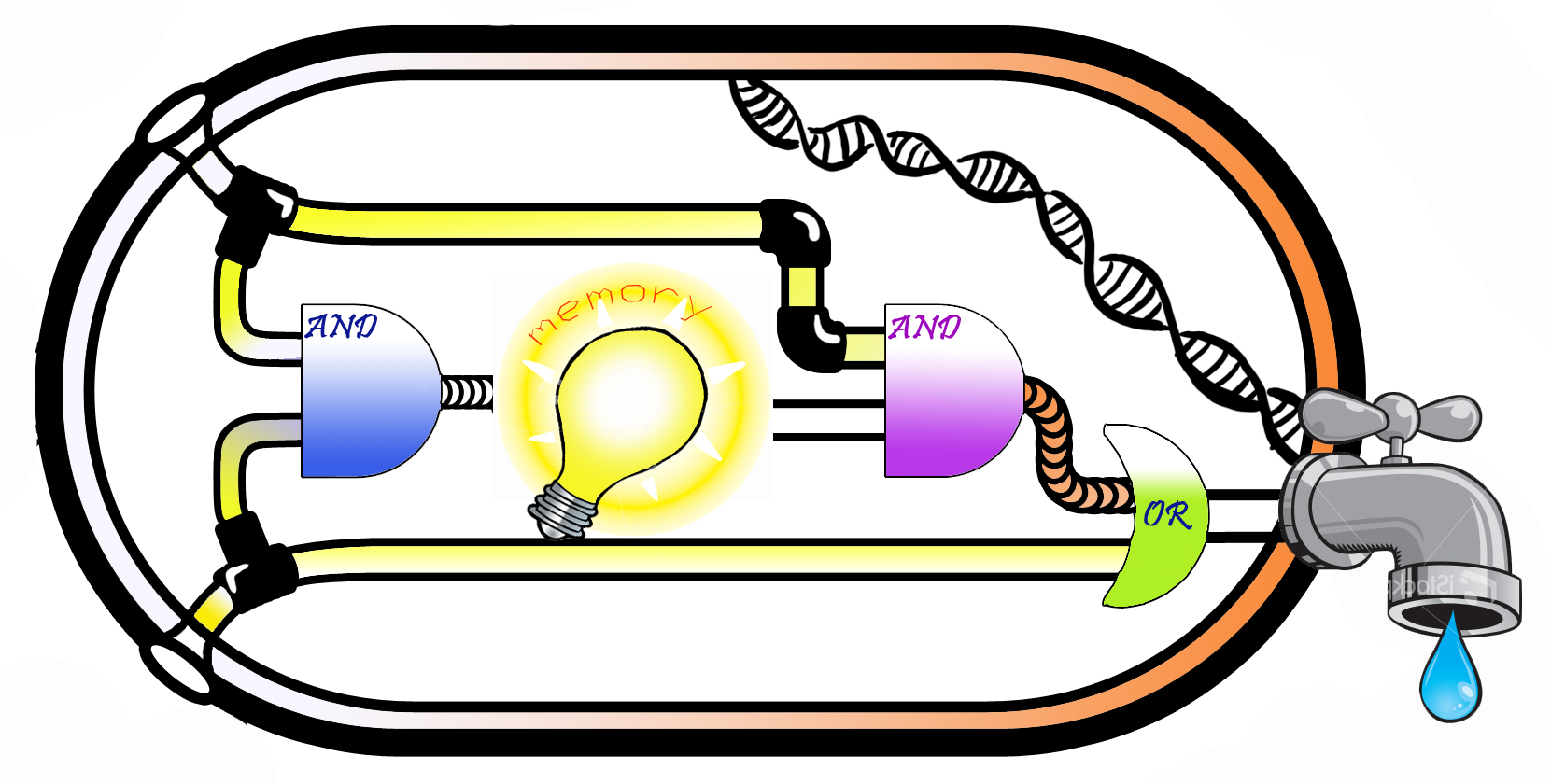 fig2. Logic Circuit of the System As it is shown above, the modules together have composed the functional system.
For convenience, we call the blue AND Gate "the 1st AND Gate", as it is closer to the inputs of the system, and the other AND Gate is called "the 2nd AND Gate". What we do after designing the logic circuit is to realize each module in biological parts and devices.
Sensor Module
The system has two input stimuli and one output reporter. When it comes to ‘’E.coli’’, the stimuli that it can sense include environmental small molecules, osmotic signal, heat, pH and so on. We picked up environmental small molecules as the food and the ring signal. Operon is a very simple functional unit in ‘’E.coli’’ which act as a small molecule sensor, for example, the lac operon can detect the existence of lactose, and give responses. There are actually many other operons that works through induction of induible promoters. In order to make the sensor itself an intact module, we packaged the activator(repressor) together with its promoter. Here we connect it to the input interface of the first AND Gate. However, it can be take down as a whole, and can be easily transplanted to other systems……
More Detailed Design of the Sensor Module is on the AND Gate 1 Design Page>Sensor Module
AND Gate Design
Many AND Gate have been designed and constructed in the past years. In our project, We adopted the design of Christopher Voigt, Which is published on Molecular Systems Biology.
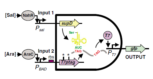 fig3. The mechanism of the AND Gate J Christopher Anderson, Christopher A Voigt and Adam P Arkin (2007) Environmental signal integration by a modular AND gate Molecular Systems Biology 3:133Fig.3 illustrates the mechanism of the design. One of the inputs of the and gate leads to the expression of T7ptag mRNA which is a T7 polymerase coding sequence with amber mutations inside. The other input of the And gate leads to the expression of supD tRNA, which is a amber mutation suppressor. The concurrence of the mRNA and the tRNA can make functional T7 polymerase, which can activate the downstream T7 promoter.
The above is used to demonstrate the mechanism of the AND Gate, this design is replicable using other activating proteins such as P2 Phage Phi activator and T3 polymerase. The output interface, of course, should also be changed to PO promoter or T3 promoter.
For Detailed Design of each of the And Gate in our system, please refer to:
AND Gate 1 Design &
AND Gate 2 Design
The Memory Module (Bistable Switch)
The Bistable Switch in our project is from Peking University iGEM 2007 Team.
The following is quoted from iGEM 2007 Peking University Project Page:
"We modify the wild type PRM/PR region of lambda phage so that it can be repressed by CI and
CI434 in opposite transcription direction. As shown in Fig3a, two different promoter designs are
considered. The first is to replace OR3 with two CI434 binding site, while the second is to add
them after OR3. Three SD signals are selected as candidates. pSB3K3 plasmid is chosen to carry
the switch. The plasmid is transformed into strain DH5alpha. The culture is then plated over
night. It turns out that the first promoter design shows bistable characteristic, namely, a
fraction of the colons express RFP while others express EGFP."

Actually, in our project, we don’t need the RFP and GFP genes downstream of the CI and CI434 gene. However, system assembly is carried out step by step, before we assembly the final system, we need adjustment when we assembly AND Gate 1 and the Bistable module. So we kept the GFP and RFP reporter for ease of first stage assembly.
OR Gate
OR Gate can be easily made by tandom promoters, activation of either promoter can lead to the downstream part expression.
In our system, the OR Gate is made up of an inducible promoter and PO/T3 promoter.
The rbs-GFP-terminator is placed downstream of the OR Gate as the output.
More Detailed Design is in the OR Gate Design Page.
^Top
|
 "
"