|
First Stage Assembly
Design
Several strategies are designed for the first stage assembly, the assembly includes three different parts that we constructed. One of them is the AND Gate Module (without output), the second is the Bistable module that we inherited from iGEM 2007 Team Peking, and the third part T7promoter CI acts as a bridge which is both the output of the AND Gate and the input to the bistable module.
Considering the size of the plasmid and replication origin compatibility of the plasmids, we draw up the following methods to assembly the system by making combinations among the available plasmids and those parts. What we wanted to do is to pick out a result that most approaches our need. And then further carry out mutation on the ribosome binding site for fine tuning if necessary.
First Strategy:
This strategy is picked because in this way the AND Gate is intact with its input and output on one plasmid. And that the bistable switch is on an independent plasmid so that it has no influence on other modules and vice versa. T7 promoter-CI is placed both upstream and downstream of the AND Gate, for the reason that they are different in their mutual influence.
The second strategy is shown below:
We make the T7promoter-CI part the same copy number as the bistable switch, to make the bistable switch easier triggered. However, this design may have larger disturbance on the bistable switch.
 fig8. Second strategy---a  fig9. Second strategy---b  fig10. Second strategy---c 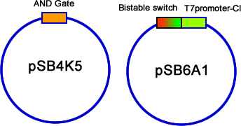 fig11. Second strategy---d
The third strategy is to put bistable switch together with the AND Gate. It is easier for the bistable module to be switched.
 fig12. Third strategy---a  fig13. Third strategy---b  fig14. Third strategy---c 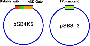 fig15. Third strategy---d
Finally, we have a 3 plasmid assembly. This design eliminates all the influences between either of the two parts.
 fig16. Forth strategy---a  fig17. Forth strategy---b The first and second method of assembly can well support second stage assembly, because the bistable switch is on relatively higher copy plasmid, coupling the next module can only have minor interference to it. The third method, although not so promising in further assembly, but we didn’t give up trying it.
For the final method, which works out (see result section), its further assembly is also promising. It is discussed in the Second Stage assembly section.
Result
Second Stage Assembly (In Process)
^Top
|
 "
"