Project > Assemble
First Stage Assembly
Design
Several strategies are designed for the first stage assembly, the assembly includes three different parts that we constructed. One of them is the AND Gate Module (without output), the second is the Bistable module that we inherited from iGEM 2007 Team Peking, and the third part T7promoter CI acts as a bridge which is both the output of the AND Gate and the input to the bistable module.
Considering the size of the plasmid and replication origin compatibility of the plasmids, we draw up the following methods to assembly the system by making combinations among the available plasmids and those parts. What we wanted to do is to pick out a result that most approaches our need. And then further carry out mutation on the ribosome binding site for fine tuning if necessary.
The bistable switch is inherited from iGEM Team Peking 2007, it is constructed to have two reporter genes on CI and CI434 side, the CI434 side is GFP gene, and the CI side is RFP gene. We kept the two reporter genes to direct our assembly. The signal is given through the AND Gate, and test whether the fluoresence state is changed.
First Strategy:
This strategy is picked because in this way the AND Gate is intact with its input and output on one plasmid. And that the bistable switch is on an independent plasmid so that it has no influence on other modules and vice versa. T7 promoter-CI is placed both upstream and downstream of the AND Gate, for the reason that they are different in their mutual influence.
The second strategy is shown below:
We make the T7promoter-CI part the same copy number as the bistable switch, to make the bistable switch easier triggered. However, this design may have larger disturbance on the bistable switch.
 fig8. Second strategy---a  fig9. Second strategy---b  fig10. Second strategy---c 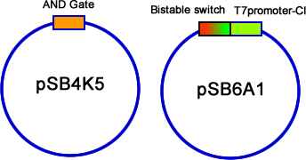 fig11. Second strategy---d
The third strategy is to put bistable switch together with the AND Gate. It is easier for the bistable module to be switched.
 fig12. Third strategy---a  fig13. Third strategy---b  fig14. Third strategy---c 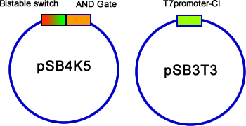 fig15. Third strategy---d
Finally, we have a 3 plasmid assembly. This design eliminates all the influences between either of the two parts.
 fig16. Forth strategy---a  fig17. Forth strategy---b
The first and second method of assembly can well support second stage assembly, because the bistable switch is on relatively higher copy plasmid, coupling the next module can only have minor interference to it. The third method, although not so promising in further assembly, but we didn’t give up trying it.
For the final method, which works out (see result section), its further assembly is also promising. It is discussed in the Second Stage assembly section.
Result
Second Stage Assembly (In Process)
Design
After the first stage assembly was finished, we designed the further step based on what we have. It is shown in the result section of the first stage assembly that the three plasmids assembly turn out to work. We designed the second stage assembly as below:
First the OR Gate-GFP module can be put on the same plasmid of the bistable switch, which has a relatively higher copy origin so that the output can be easier visualized. Actually, there is another consideration for this kind of design. Because the PhiR73 delta system is used by 2007 Cambridge team to make an amplifier, placing the PhiR73 delta(with an amber mutation) on a relatively lower copy plasmid than the output module can gain more chance that the OR gate is activated to the a similar extent when exposed to PhiR73 delta as when directly activated by salicylate. (Detailed description is on the OR Gate and Output page).
And then, the PhiR73 delta expression set, which is controlled by CI434 repressible CI activatable promoter is placed on the pSB3T3 plasmid together with the T7 promoter-CI construct. In order to reduce influence on each other, we can use PCR strategy to reverse the PhiR73 delta expression set. (Click Here for more Information of the PCR Reversing Strategy). We designed the PhiR73 delta expression set on a medium copy plasmid, because the reason we mentioned above, and another reason is that the SupD expression set has a lower copy than the PhiR73 delta expression set. As our earlier experience tell us, supD is much easier to be leaky, while the other half of the AND Gate can be controled by adjusting its rbs. SupD on a lower copy plasmid gives us more chance.
The final assembly introduced another GFP reporter (the OR Gate - GFP set), so we want to delete the GFP gene from the bistable device, while the RFP gene is kept to track the change of memory state.
Actually, our second stage assembly can be viewed as the construction of an AND Gate:
^Top
|
 "
"