Mechanism
Many AND Gate have been designed and constructed in the past years. In our project, We adopted the design of Chris Voigt[1].
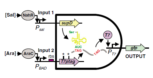 fig1. The mechanism of the AND Gate
J Christopher Anderson, Christopher A Voigt and Adam P Arkin (2007)
Environmental signal integration by a modular AND gate Molecular Systems Biology 3:133
fig1. The mechanism of the AND Gate
J Christopher Anderson, Christopher A Voigt and Adam P Arkin (2007)
Environmental signal integration by a modular AND gate Molecular Systems Biology 3:133
Fig.1 illustrates the mechanism of the design. One of the inputs of the and gate leads to the expression of T7ptag mRNA which is a T7 polymerase coding sequence with amber mutations inside. The other input of the And gate leads to the expression of supD tRNA, which is a amber mutation suppressor. The concurrence of the mRNA and the tRNA can make functional T7 polymerase, which can activate the downstream T7 promoter.
The AND Gate can be further decoupled into a input interface, a core, and a output interface.
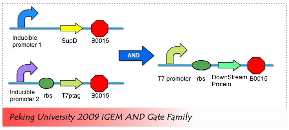 fig2. AND Gate Biological Components
The input interface includes two inducible promoter which can be induced to expression by two different environmental small molecules. Core of the AND Gate is the T7 polymerase coding sequence with amber mutations and supD tRNA. And the Output interface is actually a T7 promoter, which regulate the expression of the downstream component.
Sensor System (The input interface)
The input interface includes two inducible promoter which can be induced to expression by two different environmental small molecules.
We actually prepared five inducible promoter, and make combinations among the five promoters. The five promoters are tetR repressible promoter inducible by aTc, PBad promoter by arabinose, Lac Promoter inducible by IPTG, Salicylate inducible promoter and Lux promoter that responses to HomoSerine Lactone.
All of these inducible promoters can only work in the presence of activators or repressors, so we cloned all the activators and the repressors downstream of a constitutive promoter to make a protein generator. Then the generator is placed upstream of the corresponding inducible promoter.
There are two ways, actually, to put the generator upstream of the inducible promoter.
As shown in fig3.
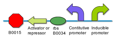
 fig3. Two ways to arrange repressor(activator) generater and the corresponding promoter
^Top
|
 "
"